Encoders
| Date Published: | |
| Last Modified: |
Overview
Encoders are devices that measure the position of something. The word ’encoder’ typically refers to a rotational encoder, although linear encoders do exist. Rotational encoders usually connect to a shaft (or have provision for one).
Incremental Encoders
Incremental encoders are encoders that output ‘step-change’ data, rather than an absolute position of an object (however, incremental encoders can have an absolute output, that typically outputs one pulse per revolution, is called channel N, and can be used to determine absolute position).
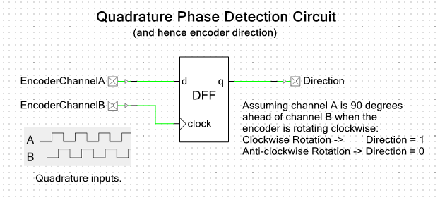
A typical output signal for is called ‘quadrature encoding’. The encoder has 2 outputs (lets call them A and B), that both output a square wave with a certain number of pulses per revolution. The square wave on channel B is phase shifted by 90° with respect to channel A. From analysing the phase difference between the two signals, the rotational direction of the encoder can be determined. For example, in the clockwise direction, channel B would be 90° ahead of channel A, and in the anticlockwise direction it would be 90° behind channel A.
The phase difference can be determined in electronics hardware by using a ‘D type’ flip-flop. The output is 1 when the encoder is spinning in one direction and 0 when spinning in the other. See the schematic below.
Overflow Protection
Overflow of encoder inputs in embedded firmware is common, because of the large ranges covered by an encoder that is connected to object which is moving quickly for long periods of time (e.g. a spinning shaft at 6000rpm).
An encoder at 6000rpm, which has 1000 counts/rev and quadrature output, is outputting 400k state changes per second. At this rate, an int32_t variable on some embedded firmware which was counting every state change would overflow after only 89 minutes (assuming the variable started at 0, and it continued to spin in the same direction).
This means that if you want to track it for longer than 89minutes, you will have to use a larger numeric type (e.g. int64_t). This is fine if you are monitoring the state changes directly with interrupts fired from changes on the quadrature pins, but what about if you are using a quadrature peripheral that returns a 32-bit number?
One way is use software overflow protection, as shown below. This takes a overflow-is-possible 32-bit number and converts it into a 64-bit number. It uses probability to determine whether an overflow has occured, based on the difference between the previous and current 32-bit value. The only requirement for this to work correctly is that it is called often enough that the encoder value cannot change more that half full-scale of the 32-bit number between two successive calls.
| |
Embedded Hardware Encoder Peripherals
The PSoC range of microcontrollers contain reconfigurable hardware that can used to make a hardware peripheral that counts quadrature output from an encoder. See the PSoC Component page for more information.
Datasheet Errors
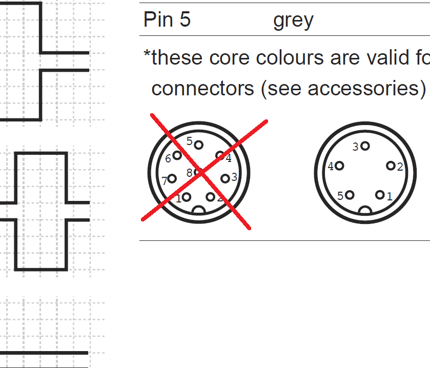
The datasheet for the Baumer BHK series of incremental encoders has an error on the encoders wiring diagram. The pinout on page (3/4) for the 8-pin connector, used for the 05A series, is mislabelled. All the pin numbers around the circumference need to be rotated anti-clockwise by one pin. Pin 2 should be pin 1, pin 3 should be pin 2, e.t.c. Pin 8 remains the same.
Authors


This work is licensed under a Creative Commons Attribution 4.0 International License .
Related Content:
- February 2016 Updates
- October 2015 Updates
- PSoC Creator
- How To Use C++ With PSoC Creator
- Using C++ With PSoC Creator