Crystals
| Date Published: | |
| Last Modified: |
Overview
Crystals are piezoelectric components which can be used to build an oscillator. Combined with driving circuitry, they form an oscillator which can be made to output a periodic waveform to be used as a clock source for digital logic (e.g. flipflops, microcontrollers, FPGAs, e.t.c.). They can also be called piezoelectric resonators.
Schematic Symbol
ERROR: fig-crystal-schematic REF NOT FOUND shows the schematic symbol commonly used for a crystal.
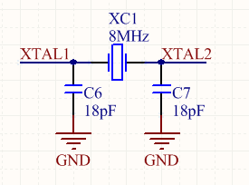
A schematic of a crystal, usually connected to a microcontroller or other digital device that uses a clock. The load capacitance usually varies from 6-25pF per leg (see the crystals datasheet for the correct value).
Equivalent Circuit
A piezoelectric crystal resonator can be modelled as a series LCR circuit in parallel with a capacitor, as shown in ERROR: fig-crystal-equivalent-circuit REF NOT FOUND.

The series components \(C_1\), \(L_1\), and \(R_1\) model the physical properties of the piezoelectric crystal, and are called the motional arm1. They are not real physical electronic components inside the crystal. The parallel component \(C_0\) is the lead capacitance2.
\(L_1\): This models the mechanical mass of the quartz in motion. Lower frequency crystals have a value of \(1-2H\) (yes, that’s whole Henries, much larger than micro/milli-Henries of most real inductors!). This value can drop down to \(1-100mH\) for the higher frequency crystals, which are smaller and therefore less mass.
\(C_1\): This models a number of mechanical properties of the quartz crystal: the stiffness, the area of the electrodes, and the thickness/shape of the wafer. The value for fundamental mode crystals ranges between \(0.005pF\) and \(0.030pF\).
\(R_1\): This models the impedance of the crystal when it is oscillating at it’s series resonant frequency. When a series LC circuit is at resonant frequency, it’s impedance is \(0\Omega\), therefore the impedance (and therefore current) is purely determined by this \(R_1\). \(R_1\) is inversely proportional to the active area of the crystal, therefore smaller crystals have a larger \(R_1\).
\(C_0\): This models the parallel capacitance (a.k.a. shunt capacitance) between the two leads of a crystal. It is the measured capacitance between the two leads when the crystal is not excited (i.e. not vibrating). \(C_0\) typically ranges from \(1-7pF\).
Series And Parallel Resonant Frequencies
The series resonant frequency \(f_S\) only depends on the motional arm (physical properties of the crystal) as shown in \(Eq.\ \ref{eq:series-res-freq}\)1.
$$\begin{align} \label{eq:series-res-freq} f_S = \frac{1}{2\pi \sqrt{L_1 C_1}} \end{align}$$The parallel resonant frequency \(f_P\) also depends on the parallel parasitic capacitance \(C_0\), as shown in \(Eq.\ \ref{eq:parallel-res-freq}\)1.
$$\begin{align} \label{eq:parallel-res-freq} f_P = \frac{1}{2\pi \sqrt{L_1 C_1}} \cdot \sqrt{1 + \frac{C_1}{C_0}} \end{align}$$The series and parallel resonant frequencies are usually very close together. Crystals below 30MHz are operated at a frequency somewhere between the series and parallel resonant frequencies1.
Important Parameters
Quality Factor
The quality factor for crystal oscillators is extremely large, typically 10,000 or greater. This is due to the very low series resistance (typically around \(5\Omega\).
The quality factor is determined by the following equation:
$$\begin{align} Q &= \frac{X_L}{R} \\ &= \frac{2\pi f L}{R} \\ \end{align}$$where:
\(X_L\) is the impedance of the inductor.
32.678kHz Crystals
32.678kHz is a popular frequency for crystals (also just shortened to 32kHz crystals) because it is exactly equal to \(2^{15}\) cycles per second. This means you can use one with a 15-bit binary counter to get a precise 1-second (1Hz) clock or “tick”. It is also a good trade-off in terms of power consumption (lower frequency = lower power consumption, great for battery powered devices) and size (higher frequency means smaller crystal package). 32.678kHz crystal are very common in any embedded circuit design which needs a real time clock (RTC). This includes RTC peripheral built into microcontrollers as well as discrete RTC ICs. As such, they are also “dirt cheap”!
Many microcontrollers have pins which you can connect a 32.678kHz crystal to, with pin names such as XTAL32, 32K_XP/32K_XN (ESP32). Sometimes the 32 is added to distinguish it from the “main” higher frequency oscillator pins, which typically support crystals in the frequency range from 1-48MHz. The microcontroller has an internal oscillator for driving the crystal. A Pierce oscillator is a popular oscillator topology used in microcontrollers to drive these crystals. For example, all of the 32.678kHz oscillators in the MSP430 range of microcontrollers use Pierce oscillators3.
As shown in ERROR: fig-tuning-fork-32.678khz-crystal-shape REF NOT FOUND, 32.678kHz crystals are also called tuning fork crystals, as the crystal is usually cut into the shape of a tuning fork1 (it vibrates in a similar manner to a large metal one used for tuning musical instruments).

Important Parameters
Frequency Tolerance
The frequency tolerance of a crystal is the accuracy of the frequency as guaranteed by the manufacturer. It is one of the most important parameters and is typically expressed in parts per million (ppm). Values between \(\pm20ppm\) and \(\pm50ppm\) are common for standard crystals (high precision crystals can have a lower ppm). Because frequency can vary significantly with temperature, the frequency tolerance is specified at a fixed temperature, usually \(25^{\circ}C\). A separate parameter, the temperature coefficient, describes how the crystal’s frequency changes with temperature.
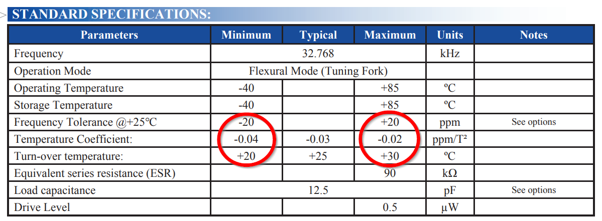
A screenshot from the Abracon ABS05 32.768kHz crystal datasheet highlighting the frequency tolerance parameters.
Temperature Coefficient and Turnover Temperature
Turnover temperature (\(T_O\)) is a term used with 32.768kHz crystals to describe the temperature at which the crystal is at it’s highest oscillation frequency. 32.768kHz crystals have a negative parabolic frequency response to temperature (frequency drops proportionally to the square of the temperature change) at the turnover temperature is at the maxima (at lower or higher temperatures, the frequency begins to drop). Most 32.678kHz crystals have a turnover temperature \(T_O\) between 20 and 30°C and \(\alpha\) of approx. \(-0.034ppm^{\circ}C^2\)4. Presumably the crystal was designed to have a turnover temperature close to nominal operating conditions to minimize the frequency change due to temperature fluctuations around operating conditions (it matters because the drift is proportional to the square of the temperature difference…it would not matter where the turnover temperature was if it was linear).
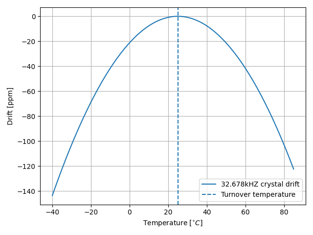
The common shape of a temperature vs. drift curve for a 32.768kHz crystal, highlighting the turnover point at the maxima. In this model, \(T_O=25^{\circ}C,\ \alpha = -0.034ppm^{\circ}C^2\).
The temperature coefficient describes how the frequency drops as the temperature moves away from the turnover temperature.
\(Eq.\ \ref{eq:32khz-drift}\) shows how to calculate the drift from the current operating temperature of the crystal.
$$\begin{align} \label{eq:32khz-drift} ppm = \alpha \cdot (T - T_O)^2 \end{align}$$where:
\(ppm\) is the drift from \(f_O\), the oscillation frequency at the turnover point, in parts-per-million
\(T\) is the operating temperature of the crystal, in \(^{\circ}C\)
\(T_O\) is the temperature at the turnover point, in \(^{\circ}C\)
\(\alpha\) is a part specific co-efficient, specified in the datasheet, in \(ppm^{\circ}C^{-2}\). If no coefficient is listed, \(\alpha=-0.034ppm^{\circ}C^{-2}\) is a good assumption
The total drift is the frequency tolerance plus this change due to the ambient temperature.
Rather than using \(ppm\), \(Eq.\ \ref{eq:32khz-drift-as-ratio}\) shows how you can instead write is a ratio of \(\frac{f}{f_O}\).
$$\begin{align} \label{eq:32khz-drift-as-ratio} \frac{f}{f_O} = \frac{\alpha}{1e^6} \cdot (T - T_O)^2 \end{align}$$where:
\(f\) is the actual oscillation frequency
\(f_O\) is the oscillation frequency at the turnover point, typically \(32.678kHz\)
Load Capacitance
Common rated load capacitances for 32.678kHz crystals includes 6pF, 7pF, 9pF and 12.5pF. The lower capacitances of 6-9pF are becoming popular for low power designs, as the higher the capacitance, the higher the current consumption. This is due to the crystal having an oscillating voltage across them (they are directly connected between the crystals outputs and ground), and the impedance of a crystal decreases (more current) with increasing capacitance[nxp-pcf85263a-rtc-ds].
Time Drift
A 32.768kHz crystal being used in an RTC will cause the time to drift slowly over, well, time :-). By how much? Let’s take the most basic approach and assume it’s only inaccuracy is it’s tolerance. Let’s assume the crystal you have chosen has a tolerance of \(\pm 20ppm\) and work out by how much it might drift over the course of a year.
The number of seconds in a year is:
$$\begin{align} t = 60*60*24*365 = 31536000s \end{align}$$\(\pm 20ppm\) of this many seconds is:
$$\begin{align} \Delta t &= \frac{20ppm}{1e6} \cdot 31536000s \nonumber \\ &= 630.7s \nonumber \\ &= 10.5\text{mins} \\ \end{align}$$So a 32.768kHz crystal with a tolerance of \(\pm 20ppm\) could drift by \(\pm 10.5\text{mins}\) each year. This is ignoring any other inaccuracies such as temperature dependence.
32.768kHz Crystal Start-Up Issues
An interesting 32.767kHz crystal start-up issue is discussed in STM’s STM32F10xx4 STM32F10xx6 Errata sheet5. Start-up issues with the LSE (low speed external) 32.678kHz crystal have been observed when there is some small amount of leakage current from the OSC32_IN and OSC32_OUT pins. This is especially true in “harsh conditions”, i.e. humid environments.
![Schematic showing an additional parallel _feedback resistor_ (shown in green) between \(16M\Omega\) and \(22M\Omega\) to prevent 32.678kHz crystal start-up issues when there is significant leakage from the crystal traces.[^bib-st-stm32f10xx4-errata].](https://blog.mbedded.ninja/electronics/components/crystals/_assets/32_678khz-xtal-start-up-issue-st-es0348-stm32f101x46-errata.png)
Schematic showing an additional parallel feedback resistor (shown in green) between \(16M\Omega\) and \(22M\Omega\) to prevent 32.678kHz crystal start-up issues when there is significant leakage from the crystal traces.5.
As shown in
ERROR: fig-32_678khz-xtal-start-up-issue-st-es0348-stm32f101x46-errata REF NOT FOUND, the solution is to place and additional \(16{-}22M\Omega\) parallel feedback resistor between the crystals pins (the OSC32_IN and OSC32_OUT tracks).
The Negative Resistance Test
The negative resistance test can be used to find the oscillator load safety margin present on your circuit design. The test is performed by inserting a potentiometer in series between the crystal and the oscillator (which may be inside a microcontroller). You then slowly increase the resistance until you find the point at which the oscillator fails to start-up correctly1.
Oven-Controlled Crystal Oscillators (OCXOs)
High-performance crystal oscillators are kept with temperature-controlled environments to increase the stability of the oscillator. They are called oven-controlled crystal oscillators (OCXOs).
A photo of an N4A series OCXO. Image from http://www.bliley.com/.
The crystals are designed to have a turning-point, a point of greatest stability, close to the oven temperature. OCXOs, rather than having a temperature stability in the ppm (parts-per-million) range like normal crystals, have a stability in the ppb (parts-per-billion) range (20ppb would be a viable stability).
Peltier devices can be used as the “oven” to keep the crystal’s temperature constant.
Popular Crystal Packages
The HC-49/U package is a popular choice for older through-hole crystals.
Newer crystals come in small, custom SMD packages, with typically either 2 or 4 pins (with the 4-pin packages usually have two GND pins).
Simulation
Crystal oscillators can be difficult to simulate accurately in most SPICE-based programs6. Most SPICE programs use the Newton-Raphson algorithm for converging to a solution. Unfortunately, the Newton-Raphson algorithm is not suitable for very high Q circuits, of which a crystal resonator is definitely one (Q values of \(10,000\) or more!). The time step has to be set so small for accurate simulation of crystal resonator circuits that it can take days of simulation to “start-up” the ceramic resonator (i.e. reach steady-state oscillation from power-on).
Crystal Component Packages
For info on crystal component packages, see the Crystal Packages page.
References
Atmel (2015, Mar). AVR4100: Selecting and testing 32kHz crystal oscillators for Atmel AVR microcontrollers. Retrieved 2021-09-12, from http://ww1.microchip.com/downloads/en/appnotes/doc8333.pdf. ↩︎ ↩︎ ↩︎ ↩︎ ↩︎ ↩︎
https://www.ctscorp.com/wp-content/uploads/Appnote-Crystal-Basics.pdf, retrieved 2021-04-28. ↩︎
Spevak, Peter and Forstner, Peter (2006, Aug). MSP430 32-kHz Crystal Oscillators. Texas Instruments. Retrieved 2021-09-10, from https://www.ti.com/lit/an/slaa322d/slaa322d.pdf. ↩︎
ST Microelectronics (2009, Jul). AN2971 Application note: Using the typical temperature characteristics of 32 KHz crystal to compensate the M41T83 and the M41T93 serial real-time clocks. Retrieved 2021-09-09, from https://www.st.com/resource/en/application_note/an2971-using-the-typical-temperature-characteristics-of-32-khz-crystal-to-compensate-the-m41t83-and-m41t93-serial-realtime-clocks--stmicroelectronics.pdf. ↩︎
ST Microelectronics (2020, April). STM32F10xx4 STM32F10xx6 Errata sheet: STM32F101x4/6, STM32F102x4/6 and STM32F103x4/6 low-density device limitations. Retrieved 2022-03-07, from https://www.st.com/resource/en/errata_sheet/es0348-stm32f101x46-stm32f102x46-and-stm32f103x46-lowdensity-device-limitations-stmicroelectronics.pdf. [nxp-pcf85263a-rtc-ds]: NXP (2023, Nov 22). PCF85263A - Tiny RTC/calendar with alarm function, battery switch-over, time stamp input, and I2C-bus [datasheet]. Retrieved 2024-01-25, from https://www.nxp.com/docs/en/data-sheet/PCF85263A.pdf. ↩︎ ↩︎
https://designers-guide.org/forum/Attachments/GEHRING_-_Fast_Crystal-Oscillator-Simulation_Methodology.pdf, retrieved 2021-04-28. ↩︎
Authors


This work is licensed under a Creative Commons Attribution 4.0 International License .
Related Content:
- Shift Registers
- Peltiers (Thermoelectric Cooler)
- Electropermanent Magnets (EPMs)
- Neon Sign Transformers
- PROFIBUS
Tags
- electronics
- components
- crystals
- MEMS
- XTAL
- XC
- XO
- OCXO
- frequency
- clocks
- power consumption
- stability
- accuracy
- ultrasonic baths
- turnover temperature